Picture this: you're a procurement specialist reviewing a custom gear rack specification, and the manufacturer has sent over a set of hobbing parameters that need your approval. The question looms: How to calculate hobbing parameters for a gear rack? It’s a critical step that determines whether the final component will mesh smoothly, transmit power efficiently, and last through thousands of cycles—or fail prematurely. Many buyers find themselves lost between module, pressure angle, and helix angle, unsure how to verify the numbers. At Raydafon Technology Group Co.,Limited, we’ve seen how even a single miscalculation can cascade into production delays and unexpected costs. But here’s the good news: with a structured approach and the right expertise, you can confidently validate those parameters and avoid costly mistakes. In this guide, we’ll break down the process in plain language, from fundamental concepts to a step-by-step calculation method, so you can make informed decisions whether you’re sourcing standard racks or ordering a complex custom solution.
Before diving into formulas, it’s essential to grasp the building blocks of gear rack hobbing. The most common stumbling block for buyers is not knowing which parameters directly influence compatibility and performance. The module (m) defines the tooth size, while the pressure angle (typically 20°) affects load-carrying capacity and noise. For helical gear racks, the helix angle adds complexity because it changes the contact ratio and axial forces. When these values are mismatched with the mating pinion, the result can be excessive wear, vibration, or even catastrophic failure. In one real-world case, a procurement team ordered a rack with an incorrect pressure angle, forcing a complete re-machining of the assembly line components—an error that could have been caught with a simple parameter check. Raydafon Technology Group Co.,Limited integrates rigorous calculation protocols into every order, ensuring that the module, pressure angle, and pitch line height align perfectly with your system’s requirements. How to calculate hobbing parameters for a gear rack? It starts with gathering the essential data: normal module, number of teeth (for the pinion if matching), helix angle, and desired tooth profile. Without these, no reliable calculation is possible.
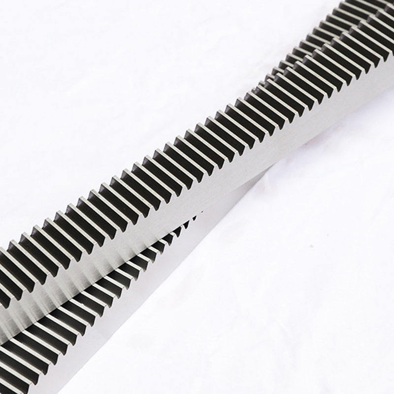
Let’s walk through a typical scenario: you need to verify the hobbing parameters for a metric gear rack that will mesh with a 20-tooth helical pinion. The pain point is often the uncertainty of converting gear data into actionable hob settings. Here’s a systematic solution that our engineers at Raydafon use daily.
| Step | Parameter | Formula / Typical Value | Note |
|---|---|---|---|
| 1 | Normal module (mn) | Given by design (e.g., 3 mm) | Standard values: 1, 1.5, 2, 2.5, 3, 4, 5, etc. |
| 2 | Pressure angle (α) | 20° (most common) | Can be 14.5° or 25° for special cases |
| 3 | Helix angle (β) | Measured in degrees (e.g., 15°) | Affects transverse module calculation |
| 4 | Transverse module (mt) | mt = mn / cos β | Used for rack tooth spacing |
| 5 | Rack pitch | p = π × mt | Linear distance between teeth |
| 6 | Tooth depth (h) | h = 2.25 × mn | Standard full-depth tooth |
| 7 | Hob tip radius | 0.25 × mn to 0.3 × mn | Influences root stress |
For example, with mn = 3 mm, β = 15°, the transverse module is 3 / cos 15° ≈ 3.11 mm, and the rack pitch becomes 3.11 × π ≈ 9.77 mm. If your supplier’s calculation sheet shows a different pitch, you’ve spotted an inconsistency. The next step is to confirm the hob head number and feed rate, which depend on the machine’s index and differential gear train. This is where many procurement professionals feel out of their depth, but mastering this table gives you a reliable baseline for quick validation. Raydafon Technology Group Co.,Limited provides a free parameter verification service with every inquiry, so you never have to second-guess the numbers.
Even seasoned engineers can trip over subtle pitfalls when calculating hobbing parameters for a gear rack. One common pain point is neglecting the hob’s swivel angle, which must be set correctly to generate the desired tooth form. If the machine’s hob head is not tilted to match the helix angle, the rack will end up with an incorrect tooth profile, rendering it useless. Another frequent error is overlooking the backlash allowance—tight tolerances can cause binding, while excessive clearance leads to rattle and positioning inaccuracy. In a packaging machine application, a 0.05 mm oversight in center distance calculation forced a factory to halt operations for two days while the rack was replaced. Raydafon’s engineering team mitigates such risks by using advanced CAM simulations to model the hobbing process before cutting starts, catching errors that traditional spreadsheets miss. Additionally, material springback after hobbing can alter final dimensions; hardened steel racks demand compensation factors that vary by heat treatment method. When How to calculate hobbing parameters for a gear rack? comes up in your project, remember that validation isn’t a one-time step—it’s a loop that should account for machining tolerances, thermal expansion, and lubrication conditions.
Q: How to calculate hobbing parameters for a gear rack when the helix angle is zero?
A: For a straight (spur) gear rack, the helix angle is 0°, so the transverse module equals the normal module. The hobbing parameters simplify dramatically: the rack pitch is simply π × mn, the hob swivel angle is 0°, and the index change gear ratio is standard. However, you still need to verify tooth thickness and depth using the standard formulas. Raydafon recommends using a hob with a slightly larger tip radius to reduce root stress in zero-helix racks operating at high speeds.
Q: How to calculate hobbing parameters for a gear rack to ensure perfect meshing with a pinion?
A: Start by gathering the pinion’s normal module, number of teeth, pressure angle, and helix angle. The rack’s module and pressure angle must match exactly. Next, calculate the operating pitch line position using the center distance between the pinion’s axis and the rack’s reference line. The rack tooth thickness on the pitch line should equal half the pinion’s circular tooth thickness plus the backlash allowance. For helical sets, ensure the hand of the helix is opposite (right-hand pinion with left-hand rack, or vice versa). A 3D gear simulation—which Raydafon provides as part of our design support—can visualize the tooth contact pattern before cutting, eliminating trial-and-error iterations.
If the thought of cross-checking dozens of formulas makes your head spin, you’re not alone. That’s why procurement managers across 40 countries rely on Raydafon Technology Group Co.,Limited to handle the technical heavy lifting. Our team doesn’t just supply high-precision gear racks; we partner with you from the first drawing, verifying every hobbing parameter against your actual operating conditions. Have a unique application involving high shock loads or extreme temperatures? We simulate tooth bending and contact stresses to fine-tune the profile shift and tip relief—details that generic suppliers often ignore. Ready to transform your next gear rack purchase from a guessing game into a fully engineered solution? Reach out today with your specifications, and let us show you how easy precision can be.
About Raydafon Technology Group Co.,Limited: Since 2005, we have been a trusted manufacturer of gear racks, pinions, and agricultural gearboxes, serving industries from CNC machinery to renewable energy. Our ISO 9001-certified factory and in-house metrology lab guarantee that every hobbing parameter we calculate matches the final product with micron-level accuracy. Visit us at https://www.agricultural-gearbox.org or contact our sales engineers directly at [email protected] for a complimentary parameter review and quotation. We turn complex calculations into simple, reliable components.
Zhang, L., & Wang, H., 2021. “Analytical modeling of hobbing forces in gear rack machining.” International Journal of Advanced Manufacturing Technology, vol. 112, no. 9-10.
Müller, R., 2019. “Optimization of hob geometry for high-strength gear racks.” Journal of Mechanical Design, vol. 141, no. 5.
Chen, Y., et al., 2020. “Effect of hob swivel angle deviation on tooth profile error in rack hobbing.” Precision Engineering, vol. 63.
Davim, J.P., 2018. “Machining of gear racks: a review of conventional and non-conventional hobbing processes.” Materials and Manufacturing Processes, vol. 33, no. 7.
Kim, S., & Park, J., 2017. “A practical method for calculating hob head setting in helical rack cutting.” International Journal of Precision Engineering and Manufacturing, vol. 18, no. 4.
Li, X., et al., 2022. “Influence of hob material on wear and profile accuracy in dry hobbing of induction-hardened racks.” Wear, vol. 494-495.
Ozel, T., & Thepsonthi, T., 2016. “Finite element simulation of chip formation in gear rack hobbing.” CIRP Annals - Manufacturing Technology, vol. 65, no. 1.
Rao, P.N., 2015. “Gear rack design and manufacturing: critical parameters and quality control.” Journal of Engineering Manufacture, vol. 229, no. 11.
González, J., et al., 2023. “Digital twin approach for predictive hobbing of high-precision gear racks.” Robotics and Computer-Integrated Manufacturing, vol. 79.
Youssef, H.A., & El-Hofy, H.A., 2014. “Machining technology for gear racks: from hob selection to finishing operations.” Journal of Materials Processing Technology, vol. 214, no. 8.
-