Picture this: at 7:42 a.m., a maintenance manager at a mining equipment plant forwards you a purchase request. The line is down, the replacement gear must be ordered today, and the drawing only says “bevel gear.” You open two supplier catalogs—one lists straight bevel gears, the other lists spiral bevel gears. Now the real question appears: What are the main differences between straight bevel gears and spiral bevel gears? If you choose the wrong tooth form, you may face whining noise at high speed, premature pitting, unexpected axial thrust on bearings, or a gear that cannot handle the torque at full RPM. For procurement teams, the difference is not only mechanical—it changes cost, lead time, installability, and after-sales risk. Raydafon Technology Group Co.,Limited regularly helps industrial buyers compare both types with application data, torque curves, and hardness maps before a purchase order is issued. In this guide, we explain the differences in plain language and give you the exact selection checklist we use in RFQs.
1. Key Differences at a Glance
2. Noise, Vibration, and Harshness (NVH) in Production
3. Load Capacity, Torque, and Gear Life
4. Manufacturing, Cost, and Lead Time
5. Application Fit and Procurement Checklist
6. Two Questions Buyers Ask Most
7. Contact and Next Steps
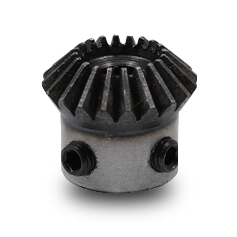
The core difference starts at the tooth line. A straight bevel gear has teeth cut straight along the cone, while a spiral bevel gear has curved, obliquely set teeth. That small geometric change creates a large difference in how force enters the mesh. A straight bevel gear engages one tooth pair at a time with a sudden line contact; a spiral bevel gear engages progressively from one end of the tooth to the other. This smoother engagement reduces impact forces, which is why spiral bevel gears often run quieter and can transmit more torque in the same space.
For buyers, the practical question is not “which is better?” but “which matches my duty cycle?” If your application runs below 800 RPM with moderate shock loads, a well-made straight bevel gear may be the most economical. If your gearbox must pass a noise test, run above 1,500 RPM, or survive frequent reversals, a spiral bevel gear is usually the safer engineering choice.
The table below summarizes the key comparison points Raydafon Technology Group Co.,Limited uses when reviewing an RFQ from an agricultural gearbox, industrial reducer, or differential drive application.
| Parameter | Straight Bevel Gear | Spiral Bevel Gear |
|---|---|---|
| Tooth engagement | Sudden, line contact | Progressive, curved contact |
| Overlap ratio | Low, about 1.1–1.4 | High, commonly 1.8–2.5 |
| Noise and vibration | Higher, especially above 1,000 RPM | Lower, smoother mesh |
| Axial thrust | Low | Higher; bearing selection is critical |
| Load capacity | Moderate | Higher for the same envelope |
| Manufacturing cost | Lower, simpler tooling | Higher, more complex machine setup |
| Typical use | Differentials, hand tools, low-speed shafts | Vehicle axles, power transmission, robotics |
Pain point scenario: A buyer replaces a spiral bevel gear in a rotary tiller with a cheaper straight bevel gear because the drawing only specifies the ratio and bore. The machine passes the first no-load test, but after two weeks in the field the housing starts whining at 1,200 RPM and the customer returns the unit. Solution: Raydafon Technology Group Co.,Limited engineers map the original contact pattern, measure the shaft angle, and confirm the thrust load direction before quoting. This prevents a low-cost part from becoming a high-cost warranty claim.
Noise complaints are one of the fastest ways to lose a repeat order. A straight bevel gear set can sound louder because each tooth enters the mesh almost instantly. At higher speeds, that impact becomes a whine or metallic knock. Spiral bevel gears, with their curved teeth and greater overlap ratio, spread the load across more than one tooth pair. This reduces the peak impact and lowers the noise floor in a well-aligned gearbox. The difference is easily noticeable above 1,000 RPM; below that speed, bearing noise and housing resonance may dominate.
Pain point scenario: An OEM assembling self-propelled sprayers tests a prototype with a straight bevel gear because it was available from stock. The dB reading at 1,800 RPM exceeds the customer’s 75 dB acceptance limit. The purchasing team is then forced to stop the line and source a different gear. Solution: Raydafon Technology Group Co.,Limited supplies spiral bevel gears with tooth flank modifications such as crowning and end relief. The adjustment keeps the contact pattern centered under load, reduces transmission error, and brings the same housing within the noise target without changing the mounting distance. In one case, changing from a straight to a spiral bevel set reduced the measured sound pressure level by 6–8 dB at the same speed, while the housing was reused with only a bearing preload change.
When you compare quotations, ask for the expected contact ratio and contact pattern specifications. A supplier that cannot provide a CMM or roll-test report may not be able to control the quality level required for quiet operation. Raydafon’s quality control includes tooth thickness measurement, contact pattern verification, and case depth inspection before shipment.
The load capacity difference is often the deciding factor when the envelope is fixed. Spiral bevel gears generally have a higher contact ratio, so the load is shared across more teeth at the same instant. That reduces bending stress at the root and contact stress on the flank. As a result, a spiral bevel gear can often replace a straight bevel gear of similar size and deliver longer life under the same torque.
Pain point scenario: A conveyor drive in a cement plant keeps failing every 14–16 months at the same tooth root. The maintenance team wants a direct replacement that fits the existing housing but must increase service life by at least 40%. Solution: Raydafon Technology Group Co.,Limited recommends a case-hardened spiral bevel set with optimized macrogeometry. By increasing the overlap ratio and adjusting the pressure angle, the new set reduces root stress and extends the service interval beyond the target. The housing and shaft remain unchanged, so the retrofit is straightforward.
Below are typical values used in first-pass evaluations. The exact numbers depend on module, material, case depth, and lubrication.
| Design input | Straight bevel gear | Spiral bevel gear |
|---|---|---|
| Recommended max pitch line velocity | Up to 5–8 m/s | Up to 20–30 m/s or higher |
| Typical contact ratio range | 1.1–1.4 | 1.8–2.5 |
| Bending stress for same torque | Higher | Lower |
| Sensitivity to misalignment | Moderate | Lower with proper tooth modification |
| Thrust load at shaft | Low | Higher; angular contact bearings may be required |
For gear life calculations, request the allowable bending stress and contact stress numbers from your supplier. Raydafon provides these values with each quotation and can run an ISO or AGMA-based rating review if you share the duty cycle.
Straight bevel gears are simpler to produce. They can be cut on older Gleason or Coniflex machines, and tooling cost is lower. This makes them attractive for prototypes, low-speed assemblies, and spare parts with urgent delivery dates. Spiral bevel gears require more advanced machines, longer setup time, and often heat treatment distortion compensation. However, the higher initial price may be recovered through longer service life and lower warranty exposure. A common mistake is to compare only the gear price and ignore the cost of bearing upgrade, housing modification, or field failure.
Pain point scenario: A procurement manager compares two quotes for a 16-tooth pinion: a straight bevel gear at $18 per part and a spiral bevel gear at $34 per part. The buyer selects the cheaper option, but the gearbox fails the OEM’s endurance test due to scoring at high RPM. The project is delayed by six weeks. Solution: Raydafon Technology Group Co.,Limited evaluates total cost of ownership rather than unit price alone. If the duty cycle includes high speed or continuous load, the spiral bevel gear usually costs less per operating hour. For low-speed, intermittent use, we may fully support a straight bevel gear to keep your machine cost competitive. This keeps the quote aligned with the actual duty cycle, not just the unit price on a spreadsheet.
Lead time is another practical factor. Because straight bevel gears need simpler tooling, small-batch delivery can often be shorter. Spiral bevel gears may require additional processing, but Raydafon maintains semi-finished blanks for common ratios and can deliver prototype sets faster than a build-from-zero process. When every day of downtime carries a cost, a slightly longer manufacturing window with a technically correct gear often beats a quick replacement that fails in service.
Application fit matters more than a generic preference. Straight bevel gears are common in differentials, hand drills, low-speed agricultural drives, and classic machinery. Spiral bevel gears dominate automotive axles, construction equipment, robotic joints, marine drives, and high-speed industrial gearboxes. The right choice depends on speed, load, noise requirements, lubrication, and bearing arrangement.
Pain point scenario: A global buyer sources a straight bevel gear for a compact hydraulic pump drive. The gear works for 300 hours, then the tooth flank shows scuffing because the pitch line velocity is higher than expected. The buyer had no application checklist from the previous supplier. Solution: Raydafon Technology Group Co.,Limited asks five standard questions before quoting: input speed, output speed, transmitted torque, shaft angle, and duty cycle. With that data, our engineers recommend whether straight or spiral teeth are appropriate and specify the necessary lubrication and surface treatment.
Use this checklist when comparing offers:
| Checklist item | Why it matters |
|---|---|
| Input and output RPM | Determines noise and scuffing risk |
| Continuous vs. intermittent load | Affects pitting and lubrication selection |
| Shaft angle and mounting distance | Prevents misalignment and edge loading |
| Housing bearing type | Spiral bevel gears may need thrust-absorbing bearings |
| Heat treatment and case depth | Controls root strength and surface durability |
| Required quality grade | Defines acceptable runout, tooth thickness, and contact pattern |
Asking these questions before ordering reduces the risk of receiving a gear that is geometrically correct but operationally wrong.
Question 1: What are the main differences between straight bevel gears and spiral bevel gears when a buyer evaluates a housing retrofit?
In many cases, a spiral bevel gear can replace a straight bevel gear, but not by simply swapping the gear. The shaft angle and mounting distance may need to be checked, and the bearing arrangement must handle the higher axial thrust of the spiral design. The contact pattern must also be re-established. Raydafon Technology Group Co.,Limited regularly supports this conversion by reviewing the housing drawing and recommending the required bearing adjustment, shimming, and tooth modification. Without this step, the gear may fit but fail early due to edge contact or bearing overload.
Question 2: What are the main differences between straight bevel gears and spiral bevel gears in terms of total lifecycle cost?
For low-speed, intermittent applications, a straight bevel gear is often cheaper in service because the initial cost is lower and the limited load exposure does not justify the added cost of spiral teeth. For continuous high-speed or high-torque use, a spiral bevel gear usually has a lower cost per operating hour because it reduces noise-related failures, pitting, and downtime. A true comparison should include energy loss, oil temperature, bearing replacement, and warranty risk.
If you are currently comparing two gear types or holding an urgent spare parts RFQ, send us the drawing, required ratio, RPM, and torque. Our engineers will respond with a technical comparison and a recommended gear type. This is the same process we use for agricultural gearbox manufacturers, industrial drive repair shops, and OEM purchasing teams.
Raydafon Technology Group Co.,Limited is a specialized supplier of bevel gears and gearbox components, known for application-focused engineering support and consistent quality control. The company helps buyers from https://www.agricultural-gearbox.org find the right gear type, material, heat treatment, and machining process for demanding power transmission applications. For technical drawings, RFQs, or sample orders, contact [email protected].
1. Litvin, F. L., Chen, J. S., Sep, T. M., & Wang, J. C. (1995). Computerized simulation of generation of spiral bevel gears. Journal of Mechanical Design, 117(2), 254–260.
2. Argyris, J., Fuentes, A., & Litvin, F. L. (2002). Computerized integrated approach for design and stress analysis of spiral bevel gears. Computer Methods in Applied Mechanics and Engineering, 191(11–12), 1057–1095.
3. Fuentes, A., Gonzalez-Perez, I., Litvin, F. L., Hayasaka, K., & Yukishima, K. (2005). Design, manufacture, and evaluation of spiral bevel gear drives with profile and lead modifications. Journal of Mechanical Design, 127(3), 483–492.
4. Simon, V. (2007). Load distribution in spiral bevel gears. Journal of Mechanical Design, 129(2), 201–209.
5. Falah, B., Gosselin, C., & Cloutier, L. (1998). Experimental and numerical investigation of the meshing cycle and contact ratio in spiral bevel gears. Mechanism and Machine Theory, 33(1–2), 21–37.
6. Lewicki, D. G., & Handschuh, R. F. (1996). Spiral bevel gear crack propagation and tooth bending fatigue life. Journal of Propulsion and Power, 12(6), 1167–1173.
7. Handschuh, R. F., & Kicher, T. P. (1996). A method for thermal analysis of spiral bevel gears. Journal of Mechanical Design, 118(4), 580–585.
8. Wang, J., & Lim, T. C. (2009). Effect of tooth mesh stiffness on the dynamic response of spiral bevel gear systems. Journal of Sound and Vibration, 319(3–5), 885–903.
9. Kolivand, M., & Kahraman, A. (2009). A load distribution model for hypoid gears using ease-off topography and shell theory. Mechanism and Machine Theory, 44(10), 1848–1865.
10. Stadtfeld, H. J. (2000). The ultimate motion graph. Gear Technology, 17(3), 14–21.
-