Picture this: you are standing in a warehouse aisle with a failed gearbox in one hand and a motor nameplate in the other. The motor says 1400 RPM, but your conveyor, mixer, or feed auger needs a much lower shaft speed. The old unit is an NMRV030 worm gearbox speed reducer, and the supplier is waiting for your replacement decision. The exact question you need to answer in the next five minutes is: How do I calculate the output RPM of NMRV030 worm gearbox speed reducer? If you guess the ratio, you risk ordering a gearbox that runs too fast or too slow, disrupts production, or forces a costly return. At Raydafon Technology Group Co.,Limited, we help procurement teams and plant engineers solve this calculation every day. Our 20 years of experience with worm gear speed reducers means we can turn a confusing spec sheet into a simple formula, a verified ratio, and a reliable replacement. In this guide, you will learn the step-by-step calculation, see a real industrial example, avoid common selection errors, and understand exactly when to contact our technical support team. No advanced math is required—just one formula, two numbers, and a clear understanding of your machine’s required speed.
Table of Contents
When a worm gearbox is replaced on a packaging machine, feed conveyor, or small agitator, the output RPM determines the exact speed of the driven shaft. A ten percent error may not sound large, but in many food-processing or agricultural applications it can mean the difference between a clean fill weight and an underweight package. The NMRV030 worm gearbox speed reducer is a compact, flange-mount or foot-mount unit commonly used with motors up to around 0.25 kW to 0.55 kW, depending on ratio and speed. Its output speed is not a random value; it is controlled by the motor input speed and the gear ratio. If you select a 10:1 ratio when the process needs 20:1, the output shaft turns twice as fast as intended. That can overload a conveyor belt or damage downstream equipment. On the other hand, a ratio that is too high makes the machine run too slowly, cutting throughput and annoying operators. Procurement teams often focus on mounting dimensions and price, but the RPM calculation should come first. Raydafon Technology Group Co.,Limited regularly guides buyers through this step before finalizing an order, because getting the speed right prevents most start-up problems.
The formula is simple:
Output RPM = Input RPM ÷ Gear Ratio
For a standard NMRV030 worm gearbox speed reducer, the input RPM comes from your electric motor. Most European and Asian industrial motors run at approximately 1400 RPM on 50 Hz power, while many North American motors run at approximately 1750 RPM on 60 Hz power. The gear ratio is stamped on the nameplate or shown in the manufacturer catalog. The NMRV030 is available in many ratios, including 7.5:1, 10:1, 15:1, 20:1, 25:1, 30:1, 40:1, 50:1, and 60:1. Because a worm gear set does not slip under normal load, the efficiency factor changes torque but does not change speed. In other words, even if the gearbox gets warm, the output RPM remains motor RPM divided by the exact gear ratio.
Here is a practical example:
| Parameter | Symbol | Example Value | Note |
|---|---|---|---|
| Motor input speed | n₁ | 1400 RPM | Read from motor nameplate |
| NMRV030 gear ratio | i | 20:1 | Confirm on gearbox tag |
| Calculated output speed | n₂ | 1400 ÷ 20 = 70 RPM | Use for shaft speed selection |
| Efficiency factor | η | 0.75–0.85 (typical) | Affects torque, not speed |
What if your motor is 1725 RPM? Simply divide 1725 by the same ratio. For a 30:1 unit, the output is 57.5 RPM. This one calculation gives you a solid baseline. If you are unsure about the ratio on your existing NMRV030, take a clear photo of the nameplate and send it to Raydafon Technology Group Co.,Limited. We can verify the exact ratio and cross-check the output speed for your machine before you place an order.
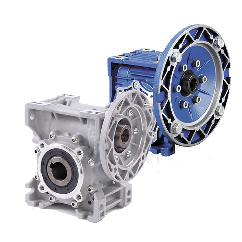
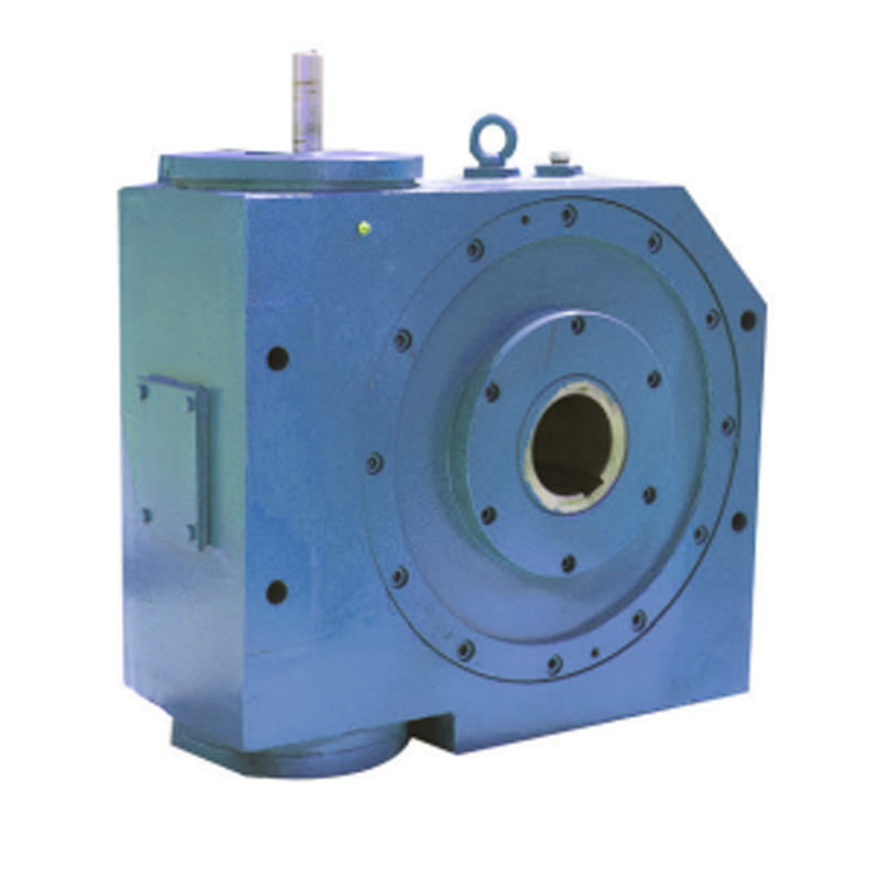
This image shows a typical NMRV040/NMRV030 worm gearbox speed reducer. The compact aluminum housing and pre-worm shaft allow fast mounting, but the ratio marking is the key to your RPM calculation.
One of the most frequent mistakes we see from buyers is adding an efficiency factor into the speed formula. A worm gearbox such as the NMRV030 wastes some input power as heat, so efficiency is typically between 70% and 85%. That efficiency is important for torque and motor sizing, but it should not be used to calculate output speed. The output shaft is mechanically linked to the worm wheel, so speed ratio stays fixed. Another error is using the wrong motor speed. A 50 Hz motor at 1400 RPM and a 60 Hz motor at 1750 RPM will produce different output speeds even with the same gearbox ratio. If you are replacing a unit in a country with dual-frequency power, always check the motor nameplate and the actual frequency at the panel. A third issue is assuming all NMRV030 units have the same ratio because they look identical from the outside. Two units can share mounting dimensions but have wildly different internal ratios. The ratio is usually marked on the housing or included in the factory part number. Finally, some buyers accidentally compare the NMRV030 to the larger NMRV040 and order the wrong frame size. The RPM formula still applies, but the larger unit may require different mounting adapters. Raydafon Technology Group Co.,Limited provides nameplate verification and ratio confirmation before shipment to help you avoid these costly mistakes.
Question 1: How do I calculate the output RPM of NMRV030 worm gearbox speed reducer if my motor is 1725 RPM and the gear ratio is 30:1?
Answer: Divide the input speed by the ratio. 1725 ÷ 30 = 57.5 RPM. At 60 Hz, this combination gives a nominal output speed of 57.5 RPM. Remember that normal worm gear efficiency losses do not reduce this speed. The output torque will be lower than the theoretical value because of friction, but the shaft speed remains fixed by the ratio.
Question 2: Does the service factor or load change the output RPM of an NMRV030 worm gearbox speed reducer?
Answer: No, the service factor does not change the output RPM. The service factor is used to make sure the gearbox can handle the load without premature wear. If a conveyor runs fully loaded or with frequent starts, you may choose a higher service factor, but the speed is still calculated as motor RPM divided by gear ratio. The only exceptions are extreme overload or mechanical failure, which are outside normal selection conditions. For demanding applications, contact Raydafon Technology Group Co.,Limited and we will check both speed and torque margins with you.
When you send us a motor nameplate photo and the existing NMRV030 gearbox tag, we do more than quote a price. Our engineers check the ratio, output RPM, mounting style, bore size, and expected torque. If your application has changed—for example, a faster conveyor or a heavier mixer—we can recalculate the output speed and suggest a different ratio or motor. Because Raydafon Technology Group Co.,Limited specializes in worm gear speed reducers and agricultural gearbox solutions, we keep a wide range of NMRV030 and NMRV040 combinations ready for quick delivery. That means fewer days waiting on a wrong part and fewer production headaches. We also provide installation guidance so your maintenance team can confirm the shaft speed on site. The goal is simple: you should never have to guess the answer to “How do I calculate the output RPM of NMRV030 worm gearbox speed reducer?” We help you calculate it, verify it, and order with confidence.
Still unsure about your NMRV030 output RPM? Send your motor speed, gearbox ratio, and application details to [email protected], and our team at Raydafon Technology Group Co.,Limited will verify the calculation and recommend the right worm gearbox speed reducer. Visit us at https://www.agricultural-gearbox.org to explore our full range of agricultural gearboxes, speed reducers, and replacement units. With 20 years of experience, we support procurement managers and plant engineers from initial RPM calculation to final installation, so your production line keeps moving.
Reference list
Simon, V. (1994). Load distribution in cylindrical worm gears. Mechanism and Machine Theory, 29(1), 67–82.
Sohn, J., and Park, N. (2017). Geometry design of worm gear drives with improved efficiency. Journal of Mechanical Science and Technology, 31(6), 2767–2774.
Baglioni, S., Cianetti, F., and Landi, L. (2012). Influence of addendum modification on worm gear efficiency. Mechanism and Machine Theory, 53, 113–127.
Xu, H., and Kahraman, A. (2007). Prediction of mechanical efficiency of parallel-axis gear pairs. Journal of Mechanical Design, 129(1), 58–68.
Sharif, K. J., Kong, S., Evans, H. P., and Snidle, R. W. (2001). Contact and elastohydrodynamic analysis of worm gears. Proceedings of the Institution of Mechanical Engineers, Part C: Journal of Mechanical Engineering Science, 215(8), 1121–1130.
Milosavic, B., and Mitrovic, R. (2019). Influence of gear ratio and oil viscosity on worm gear efficiency. Tribology International, 133, 108–116.
Chen, Y. C., and Tsay, C. B. (1996). Mathematical model of worm gear drives with localized bearing contact. Mechanism and Machine Theory, 31(8), 1043–1054.
Dudás, I. (2000). Modelling and simulation of a new worm gear drive with improved bearing contact. Mechanism and Machine Theory, 35(11), 1569–1582.
Kapelevich, A., and McNamara, T. (2010). Direct gear design for high-performance transmissions. Gear Technology, 27(3), 54–61.
Idler, S., and Witting, K. (2018). Thermal and efficiency modeling of small worm gearboxes. Journal of Mechanical Science and Technology, 32(10), 4651–4659.
-