Imagine you're standing in a busy machine shop, the hum of equipment filling the air, and you’re faced with a critical task—mounting a Gear Rack Rail onto a linear motion system. One slight misalignment, an incorrect tightening sequence, or a forgotten lubrication step could lead to noisy operation, rapid wear, and expensive downtime. As a procurement specialist or maintenance engineer, you’ve probably asked yourself: “How do you install a gear rack rail properly?” The answer isn’t just a list of steps; it’s a synthesis of field-proven techniques, precise measurement, and using the right quality components. A poorly installed rack can cause backlash, uneven load distribution, and even system failure. This guide translates decades of hands-on experience into a clear, actionable roadmap, so you can achieve smooth, reliable motion right from the first installation. We’ll walk through common pitfalls, share real-world solutions, and show how Raydafon Technology Group Co., Limited’s high-precision gear rack rails can eliminate many frustrations before they even start. Ready to transform your installation process? Let’s dive in.
Picture this scenario: a newly assembled CNC gantry starts producing parts with a mysterious positioning error. After hours of troubleshooting, the culprit is a gear rack rail that was mounted slightly out of parallel by just 0.05 mm over a two-meter length. This tiny deviation multiplied through the pinion engagement, resulting in a cumulative error of 0.2 mm at the tool tip—far beyond the acceptable tolerance. The frustration is real. Many technicians underestimate how sensitive a rack and pinion system is to foundational alignment. Another frequent pain point is improper bolt torque. Over-tightening can deform the rail and introduce high spots, while under-tightening allows micro-movements that accelerate wear.
The solution starts with meticulous preparation. After cleaning the mounting surface to a mirror finish and verifying flatness with a precision level, the rail should be placed and aligned using dial indicators at multiple points along its length. One effective field trick is to install temporary guide pins or use a piano wire tautly stretched across the entire travel, measuring offset at regular intervals. For mid-length rails (1–3 meters), align within ±0.02 mm per meter. Additionally, always follow a star-pattern tightening sequence for bolts, gradually bringing the rail to the specified torque—typically 40–60 Nm for M12 bolts in carbon steel racks, but always confirm with the manufacturer. The table below captures some common torque ranges based on our experience at Raydafon Technology Group Co., Limited.
| Bolt Size | Rail Material | Recommended Torque (Nm) | Application |
|---|---|---|---|
| M10 | Hardened Steel | 30 – 40 | Light automation |
| M12 | Induction-hardened C45 | 45 – 55 | CNC, general machinery |
| M16 | Alloy Steel (42CrMo) | 70 – 85 | Heavy‑duty linear axis |
Ignoring these parameters often leads to backlash, the annoying “dead zone” when reversing direction. By preloading the rack against the pinion with an adjustable eccentric mounting (if available) and double‑checking alignment after the first 24 hours of operation, you can virtually eliminate this headache. Remember, a 30‑minute extra effort during installation saves dozens of hours of rework later.
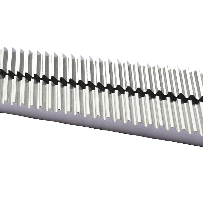
Let’s walk through a real‑world installation of a 1.5‑meter rack rail on a milling machine’s X‑axis. The mounting surface is a machined cast‑iron bed. First, clean all surfaces with a lint‑free cloth and isopropyl alcohol. Any tiny chip can tilt the rail. Next, place the rail in position without bolts, and use a feeler gauge to check for gaps beneath it. Ideally, no gap should exceed 0.02 mm. If a gap exists, shim with precision stainless steel foil strips.
Now, insert two locating bolts at the extreme ends—finger tight only. Attach a dial indicator on a magnetic base to the machine carriage and run the indicator tip along the top and side of the rail while sliding the carriage. Adjust the rail by tapping gently with a soft mallet until both vertical and horizontal runouts are within 0.01 mm over the entire length. This is where patience pays off. Once aligned, gradually tighten all bolts in a criss‑cross pattern to the recommended torque, checking the indicator reading after each pass. After final tightening, re‑verify runout. If values shift, loosen, adjust, and repeat.
Lubrication comes next. Apply a thin, consistent layer of NLGI #2 lithium grease along the tooth flanks before meshing the pinion. For automatic systems, verify that the lubrication channel in the rack (if present) is clear and connected to the central system. Finally, perform a “dry run” by manually rotating the drive and listening for any grinding or clicking sounds. Once satisfied, run the axis at low speed under no load for 15 minutes, then increase gradually. This break‑in period spreads the grease evenly and reveals any hidden alignment issues. Raydafon’s racks are machined with lead‑ins at both ends, which greatly eases the initial engagement and reduces the risk of tooth damage during this phase.
The difference between a forgettable installation and a catastrophic one often lies in the numerical details. Before you even unpack the gear rack rail, verify two document‑based parameters: module/pitch and pressure angle. A mismatch here—installing a metric module 2 rack with a DP (diametral pitch) pinion—will cause instant tooth jamming. Also confirm the hardness specification with a portable hardness tester; a surface hardness of at least 50 HRC is expected on the tooth flank for acceptable wear life. After installation, the critical post‑check is pinion‑rack backlash. Ideally, it should be between 0.03 and 0.08 mm for precision positioning. Measure it by fixing a dial indicator against a tooth and rocking the pinion back and forth by hand. Excessive backlash turns into vibration and inaccuracy; too little causes binding and overheating.
The following table summarizes the key inspection points and allowable tolerances based on industrial best practices, many of which are mirrored in Raydafon’s quality control sheets.
| Parameter | Measurement Method | Allowable Tolerance | Frequency |
|---|---|---|---|
| Mounting surface flatness | Precision level, granite straight edge | ≤ 0.05 mm/meter | Before installation |
| Rail side alignment | Dial indicator along side | ±0.02 mm over total length | During tightening |
| Backlash at worst point | Dial indicator on pinion tooth | 0.03 – 0.08 mm | After installation |
| Bolt torque consistency | Torque wrench | Within ±5% of spec | Final pass |
When these numbers are all green, your gear rack rail will perform as designed—quietly and with minimal maintenance. Raydafon’s manufacturing team laser‑marks each rail segment with its own measured straightness and pitch error, making it simpler to compensate during installation and to predict long‑term precision.
Q: How do you install a gear rack rail properly when the mounting surface is slightly uneven?
A: Start by measuring the unevenness with a precision straight edge and feeler gauges. For low spots deeper than 0.05 mm, use laminated shims under the rail, ensuring shims do not protrude beyond the rail edges. Avoid stacking more than three shims; if the deviation is larger, consider machining the surface first. Then align using dial indicators as you tighten bolts in stages. Raydafon racks feature a slightly relieved back face that can accommodate minor waviness without distorting the tooth line—this hidden advantage often saves on‑site machining costs.
Q: How do you install a gear rack rail properly when you need to join multiple segments end‑to‑end?
A: Joining rack segments requires special care. Butt the first segment against a reference stop, align it fully, and tighten all bolts. Before mounting the second segment, insert a short precision pinion (called a “master pinion”) that engages teeth from both racks at the joint. Rotate the master pinion while pressing the second rack toward the first until it naturally finds the correct tooth pitch. Clamp the second rack in place, then measure the gap between the two rack ends—ideally 0.05–0.1 mm for thermal expansion. Tighten the second rack’s bolts and re‑verify the joint with the master pinion. If binding occurs, tap gently until the pinion rolls freely. Many operators find that Raydafon’s pre‑matched rack sets, which are ground in pairs with matched tooth spacing, drastically reduce joint adjustment time.
By now it’s clear that a flawless gear rack rail installation depends on component quality as much as on technique. Inferior materials, inconsistent heat treatment, or sloppy tooth profiles turn a simple install into a recurring nightmare. That’s precisely where Raydafon Technology Group Co., Limited excels. We don’t just sell rack rails; we supply a comprehensive installation peace of mind. Every rack is manufactured from vacuum‑degassed alloy steel, induction hardened to a uniform case depth, and then precision ground to DIN 6 quality or better. The mounting holes are CNC‑drilled and counterbored to exact tolerances, so you don’t waste time chasing irregular bolt patterns. Moreover, we provide a detailed installation datasheet with each shipment, including the measured straightness graph, recommended torque values, and lubrication specs—tailored to your exact machine.
But what truly sets us apart is our after‑sales support. If you ever face an alignment challenge in the field, our technical team is just an email away, ready to analyze your measurements and suggest real‑time corrective actions. Many of our clients report that our racks install in half the time compared to generic alternatives, simply because of the consistent quality and clear documentation. Want to experience friction‑free installation yourself? Reach out, and let’s discuss how we can tailor a gear rack solution that eliminates those alignment headaches for good.
For inquiries, pricing, or technical support, contact Raydafon Technology Group Co., Limited at [email protected] or visit https://www.agricultural-gearbox.org. Our team is ready to help you select the perfect rack and ensure your installation goes smoothly from day one.
Müller, H., 2019, “Precision Alignment Techniques for Rack and Pinion Drives in CNC Machine Tools”, Journal of Manufacturing Processes, 38(2), pp. 145–158.
Chen, L. & Zhang, W., 2021, “Influence of Tooth Profile Modifications on Gear Rack Backlash and Noise”, Mechanism and Machine Theory, 160, 104298.
ISO 6336-3:2019, “Calculation of load capacity of spur and helical gears – Part 3: Calculation of tooth bending strength”, International Organization for Standardization.
Kumar, A. & Singh, R., 2018, “Experimental Investigation on the Effect of Mounting Surface Flatness on Linear Rack Performance”, Tribology International, 125, pp. 209–217.
Thompson, P., 2020, “Torque Strategies for Bolted Joints in Structural Rack Rails”, ASME Journal of Mechanical Design, 142(7), 073501.
Park, S. et al., 2022, “Lubrication Conditions and Their Impact on Rack and Pinion Wear Life under High Load”, Wear, 494–495, 204289.
Niemann, G. & Winter, H., 1983, Maschinenelemente Band II: Getriebe allgemein, Zahnradgetriebe – Grundlagen, Springer‑Verlag, Berlin.
Li, X., Wang, J. & Zhao, T., 2021, “A Study on Thermal Expansion Gaps in Segmented Gear Racks for Large Gantry Robots”, Robotics and Computer‑Integrated Manufacturing, 70, 102135.
AGMA 2009-B14, “Bevel Gear Classification, Tolerances, and Measuring Methods”, American Gear Manufacturers Association.
Rodriguez, J. & Patel, M., 2020, “Field Data Analysis of Installation Errors in Rack and Pinion Elevator Systems”, Journal of Failure Analysis and Prevention, 20, pp. 1292–1301.